TRIANGLE
“What is a man? A miserable little pile of secrets!”
Dracula, “Castlevania: Symphony of the Night”
Indeed, what is a triangle?
And why it’s such a big deal? Can’t you do 3D graphics without triangles?
Of course you can.
For one, what we’re trying to do here is called rasterization, as already mentioned in the “Line” chapter (you can also check this Wikipedia article for more details), but there is another way of rendering 3D images called ray tracing. It actually might be conceptually easier (there’s well known local meme in computer graphics about how you can fit raytracer code on a business card), but traditionally it’s much more computationally expensive (even at the time of writing this), so that’s why most of the time people use rasterization instead. Please research this topic yourself, if you like. You can start, for example, here.
From the rasterization point of view, one notable example is Sega Saturn that used quads instead of triangles to render 3D. This doesn’t mean that Sega Saturn couldn’t draw triangles - it just used quad as its main rendering primitive. And before you start wondering, it was backed by none other than Nvidia back then. I’m pretty sure that earliest examples of 3D graphics also used triangles (well, for the most part at least, as far as I can tell from the video). So why rectangles then? Well, one of the explanations is that this was done to achieve performance in drawing of tile-based scenes, i.e. 2D sprites. It was sort of an inertia from the times of NES and SNES, which used tile-based rendering of sprites. Here’s a link to a YouTube video about Sega Saturn someone made in case you’re interested.
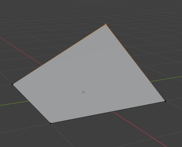
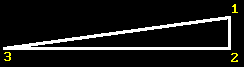
But eventually everybody kinda silently agreed upon triangles and for obvious reason: it’s the simplest polygon possible. Triangle is unambiguously defined by any 3 points and they always reside on the same plane in space, while with quads you could get for example this:
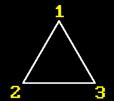
So now we know that any 3D model (no matter how fancy) is actually consisting of lots of triangles. Thus, before we start drawing such 3D models we need to learn how to draw triangles first. Given three points on a screen we need to somehow decide which pixels to light up so that the area of a triangle looks filled.
To do that we’re going to implement what’s called scanline rasterization method: we will traverse a triangle from top to bottom and connect with a horizontal line two points on triangle’s left and right edges, hence the name scanline. Fast and easy.
Scanline rasterizer
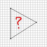
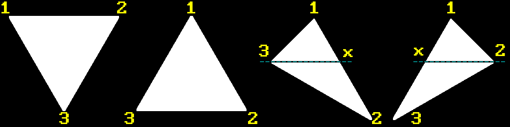
If you actually think about it, aside from degenerate cases like a line or a point, any triangle can belong to one of the three categories, one of which can be further divided into two more. But both of them contain previous two (I marked it with a dashed line for clarity), so we have four categories in total:
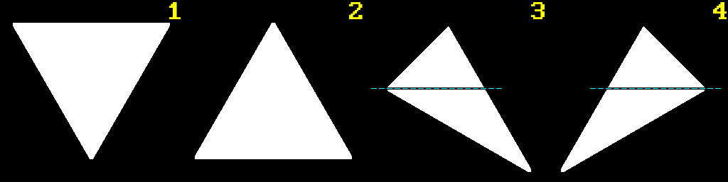
We will call these:
-
Flat Top (FT) triangle
-
Flat Bottom (FB) triangle
-
Composite Major Right (CMR) triangle
-
Composite Major Left (CML) triangle
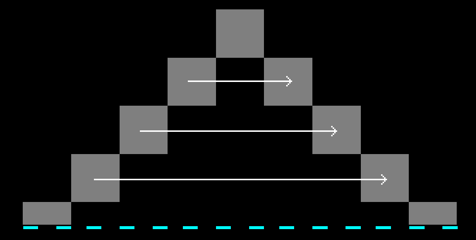
As you can clearly see, CMR and CML triangles consist of FB and FT triangles (let’s call them basic triangles) if looking from top to bottom. Thus, in general every non-degenerate triangle can be represented with basic triangles. So what we need to do is find out which type of triangle is before us and then perform our scanline rasterization by filling in pixels going left to right, top to bottom across triangle’s edges, like so (FB triangle shown):
To do that we will use our old friend from previous chapter - Bresenham algorithm. Remember earlier I said that we will use it, but a bit indirectly? What I meant is that we’re not going to use it to draw lines with it - we’re going to use it to get points across edges of corresponding triangle, and then we will connect them horizontally at each $Y$ pixel position.
Let’s recall that our line drawing algorithm has certain quirk, so to speak: it swaps points depending on the line’s slope. And the side effect of this is that our first point might be either above or below the second:
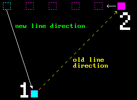
But since we’re planning on doing scanline rasterization, it would be more convenient to always have first point above the second. That’s actually easy to do - we just need to sort line points by $Y$ instead of $X$ and then basically swap everything inside the algorithm. I’ll leave that as an excercise to the reader. Start with the similar setup as the original one, but this time consider line with steep slope as your “base case”, and then just follow along with the whole thinking process from previous chapter again and you’ll be fine.
And to make our life easier let’s wrap that in generator-like class that is initialized with start and end points, and when called returns next point along a line between these two points until there are no more points left, like this:
BLG bg;

bg.Init(x1, y1, x2, y2);

BLG::Point* p = bg.Next();
while (p != nullptr)
{
  printf("(%d, %d)\n", p->first, p->second);
  p = bg.Next();
}
See implementation and example here.
Then we can use two instances of such class to create two generators that will return corresponding points of a triangle’s edges that we need to connect.
Now that we’ve prepared everything, let’s continue with the triangle. There will be quite a lot of written text onwards, but I think that it will be a great example of how a problem that is simple at first glance becomes overgrown with lots of details that you might’ve not known or thought about.
Now, since we have only four different possible triangles, let’s enumerate their vertices. Because we’re going to use vertices in calculations we need to be able to address them somehow, right? Which brings us to the question of winding order, because we need some kind of, well, order in which we’re going to enumerate vertices. For example, should it be like this:
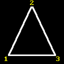
Or this:
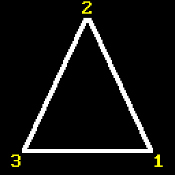
Or what if we “bit-shift” points across (first becomes second, second becomes third and third becomes first)? And this is just for one type of triangle. I guess theoretically you could just write code for every possible scenario, but that will be a maintenance nightmare and kinda unprofessional. Like, do we really have no choice but to manually go through all possible cases? Spoiler alert: of course not. So let’s think about it.
Recall that a little bit earlier we introduced a generator class that produces points for a line that always start from the top? We did that because for scanline rasterization it’s natural to always start from the top. This fact actually narrows down possible configuration of vertices: our first point of any triangle will always be at the top. So that leaves the question of how we enumerate the rest - CW or CCW?
Let’s pick CW order because it seems that it’s the one that is used across all learning materials that I encountered regarding this topic. And honestly CW is kinda more easy to the mind: on the screen (0;0) is at the top-left corner and x and y go left to right, top to bottom, so CW ordering feels more natural here. Also, as a bonus, by sticking to CW order we will shorten amount of additional swap operations, as you’ll see later.
Sure, one could say that by choosing the same winding order for both 2D and 3D (we’ll use winding order to determine certain properties there as well) we would attain sort of a consistency. That’s actually exactly what I contemplated about for a bit, but it really is just a matter of preference, and winding order for 3D is not related at all to the order that we can choose for 2D rasterization, so let’s not make our life harder than it already is. ;-) But if you do want to complicate your life and choose another winding, you probably already guessed that you would just need to “flip everything” around that is shown in the example.
So, it would be great if we could “convert” any given three vertices to only one configuration that we can work with. Let recall our four possible triangles again:
Actually, by sorting vertices $Y$ first and $X$ second, they will position themselves like so:
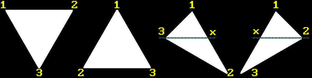
Which is almost what we need. All that is left for us to do is to perform only one swap of vertices 2 and 3 for FB triangle:
In order to draw composite triangles we can always just manually specify proper order for their FT and FB triangles that they consist of. And that’s it, we have our enumeration order:
FT  - 1, 2, 3
FB  - 1, 2, 3
CMR - [ (1, x, 3), (3, x, 2) ]
CML - [ (1, 2, x), (x, 2, 3) ]
We still need to find splitting point x to be able to rasterize composite triangle using two basic ones.
Let’s look at CMR triangle as an example more closely:
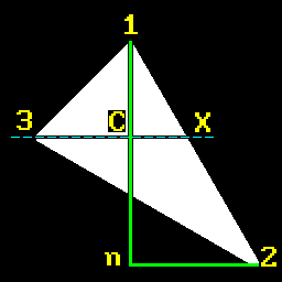
We can observe that triangles 1CX and 1n2 are similar. From this fact we can express similarity ratio:
Obviously, $X.y=v_3.y$ and $n.x=v_1.x$.
Abusing the same similarity property we can also write:
Which allow us to equate both expressions:
\[\frac{X.x-v_1.x}{v_2.x-v_1.x}=\frac{v_3.y-v_1.y}{v_2.y-v_1.y}\]From which we can express $X.x$ by cross-multiplication:
\[\begin{align*} (X.x-v_1.x)(v_2.y-v_1.y)&=(v_3.y-v_1.y)(v_2.x-v_1.x) \\ X.x-v_1.x&=\frac{(v_3.y-v_1.y)(v_2.x-v_1.x)}{(v_2.y-v_1.y)} \\ X.x&=v_1.x+\frac{(v_3.y-v_1.y)}{(v_2.y-v_1.y)}(v_2.x-v_1.x) \end{align*}\] \[\boxed{X.x=v_1.x+r(v_2.x-v_1.x)}\]OK, so to outline our steps, for any given triangle we do the following:
-
Sort vertices Y first and X second.
-
Check if triangle has CCW winding. If it does then it can only be a FB triangle and in that case we need to swap its 2 and 3 vertices. Otherwise do nothing.
-
Perform rasterization.
How can we determine current winding order of a triangle?
To do that we’re going to use what’s sometimes called 2D cross product, but actually it’s just a normal cross product with Z set to 0. One can easily memorize how to perform a cross product on two vectors if you’ll associate the word cross with the following mnemonic:
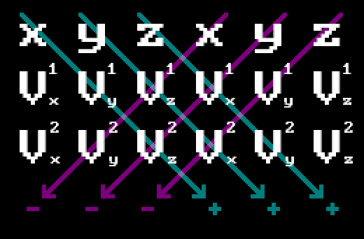
Thus we will have:
\[\vec{V_1} \times \vec{V_2} = (V^1_yV^2_z-V^1_zV^2_y,\;V^1_zV^2_x-V^1_xV^2_z,\;V^1_xV^2_y-V^1_yV^2_x)\]You can see that by setting Z component of vectors to 0 you’ll be left with:
Since right now we’re doing 2D and not interested in this being interpreted as a 3D vector (you can still think of it as a vector going outside / inside the screen, if you like), we can just use the last component as a scalar value:
double CrossProduct2D(const Vec3& v1, const Vec3& v2)
{
  return (v1.X * v2.Y - v1.Y * v2.X);
}
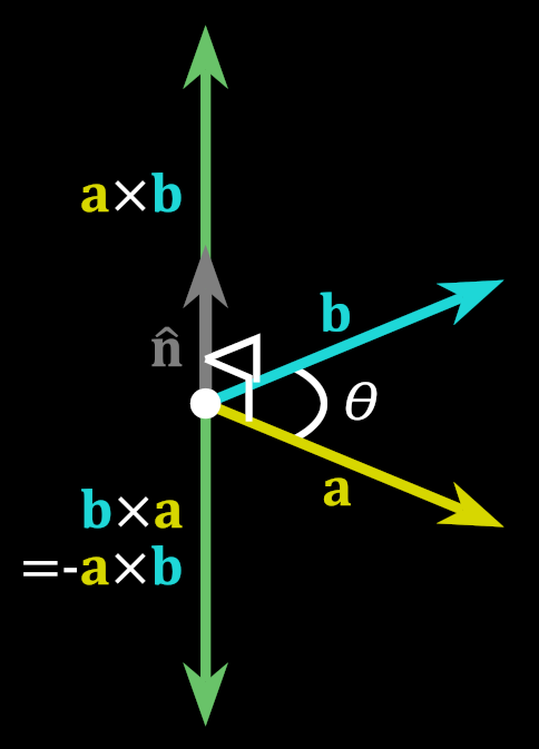
Let’s recall that the result of a cross product differs by the sign depending on the order of operations:
Let’s again look carefully at this example triangle:
To determine current winding order all we have to do is note that if we take a cross product of vectors 1-2 and 2-3, it will yield different sign depending on the order of vertices. It might not be obvious, so I’ll demonstrate with a picture on a CW ordered triangle. The picture is not 100% accurate in terms of measures, but enough to relate the main idea:
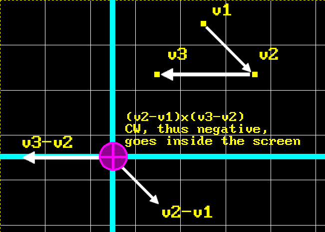
Back at the university I was introduced to this handy convention to represent vectors that go towards or from your face. The weird cross on pink circle represents imaginary arrow’s feathers to highlight that vector goes inside the picture. Conversely, vector that goes towards you would be represented by a circle with a dot inside of it, highlighting imaginary arrow’s head. As you can see, order of operations for cross product on two difference vectors goes in CW direction in this example, yielding negative result, so resulting vector goes inside the screen. Thus, winding order of this triangle is CW.
Hint: direction of a resulting vector from difference of two vectors is always pointing to the vector from which subtraction was performed. Remember, that you can always translate a vector to have its origin at (0, 0) while preserving direction, and then your vector can be described using just a point. Like in the picture above: vectors v1, v2 and v3 have their origin at (0, 0).
Here’s how it’s implemented in code:
WindingOrder GetWindingOrder(const TriangleSimple& t)
{
  double cp = CrossProduct2D(t.Points[1] - t.Points[0],
                             t.Points[2] - t.Points[1]);

  return cp > 0 ? WindingOrder::CW : WindingOrder::CCW;
}
Where WindingOrder is just a simple enum:
enum class WindingOrder
{
  CW = 0,
  CCW
};
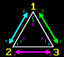
Now back to the example triangle from before. It has CCW winding order, obviously, and we need CW. But you can see that winding order changes if we swap any of the two vertices:
So, after we find out winding order of a triangle, we can check if it’s the one we need, and “fix” it if it’s not. So let’s put all of that in a helper function:
void CheckAndFixWinding(TriangleSimple& t)
{
  WindingOrder wo = GetWindingOrder(t);
  if (wo == WindingOrder::CCW)
  {
    //
    // Since we decided to stick to CW winding order if we encountered CCW one
    // just swap two adjacent vertices to change it.
    // We will swap 2nd and 3rd because we decided on certain configurations
    // of vertices for all triangle types.
    //
    std::swap(t.Points[1].X, t.Points[2].X);
    std::swap(t.Points[1].Y, t.Points[2].Y);
  }
}
As you can see from the comment, we will swap second and third vertex and not just any random two, because, remember, that’s the only case when we get CCW order after sorting - FB triangle, where we need to swap vertices 2 and 3.
Just a side note: you can’t determine winding order of a triangle in 3D space because there’s always the “other” side, so whatever is CW looking from the “front”, it’s CCW looking from the “back”. But here we’re in 2D screen space, so there’s no “other” side, and thus we’re good here.
And with that, here’s how our main rasterization function looks like:
void FillTriangleCustom(TriangleSimple& t)
{
  SortVertices(t);
  CheckAndFixWinding(t);

  TriangleType tt = GetTriangleType(t);
  switch (tt)
  {
    case TriangleType::VERTICAL_LINE:
      DrawVL(t);
      break;

    case TriangleType::HORIZONTAL_LINE:
      DrawHL(t);
      break;

    case TriangleType::FLAT_TOP:
      DrawFT(t);
      break;

    case TriangleType::FLAT_BOTTOM:
      DrawFB(t);
      break;

    case TriangleType::MAJOR_RIGHT:
      DrawMR(t);
      break;

    case TriangleType::MAJOR_LEFT:
      DrawML(t);
      break;

    default:
      break;
  }
}
We’re also handling two edge cases here when triangle has degenerated into a line, but they’re trivial to implement, so I won’t be showing them here. Instead let’s look at DrawFT() for rasterization of a flat top triangle:
void DrawFT(const TriangleSimple& t)
{
  //
  // Vertices in 't' are always:
  //
  // 1     2
  //
  //
  //    3
  //
  BLG first;
  first.Init(t.Points[0].X, t.Points[0].Y, t.Points[2].X, t.Points[2].Y);

  BLG second;
  second.Init(t.Points[1].X, t.Points[1].Y, t.Points[2].X, t.Points[2].Y);

  if (Wireframe)
  {
    RasterizeWireframe(first, second, t, TriangleType::FLAT_TOP);
  }
  else
  {
    Rasterize(first, second, t, TriangleType::FLAT_TOP);
  }
}
As you can see, our sorting and widing fixing allowed us to rely on specific order of vertices that come into this function. Then we can prime two generators for two corresponding edges: 1-3 and 2-3. Again, you can see that there’s another convenient method present for drawing wireframe triangle, but we’re also going to skip it since it’s trivial and not important for this topic.
Now, Rasterize() is where things get real. This function contains code for rasterization of both FT and FB triangles. But before checking it out we need to address another issue.
Generally it’s obvious that during scanline rasterization loop we need to connect leftmost points of the left line with rightmost points of the right line, like so:
But consider the following configuration:
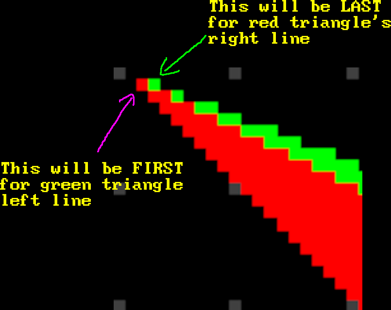
In this case there is an extremely gentle slope of one side of a triangle (1-3) which will have more points with the same $y$ compared to the other side (1-2) which has few points, all of which with different $y$. What this means is that if we just let the algorithm run and connect any two points, produced by generators, across a scanline with the same $y$, we will overdraw this line multiple times, because edge 1-2 will have to wait several turns before point from edge 1-3 changes its $y$ coordinate.
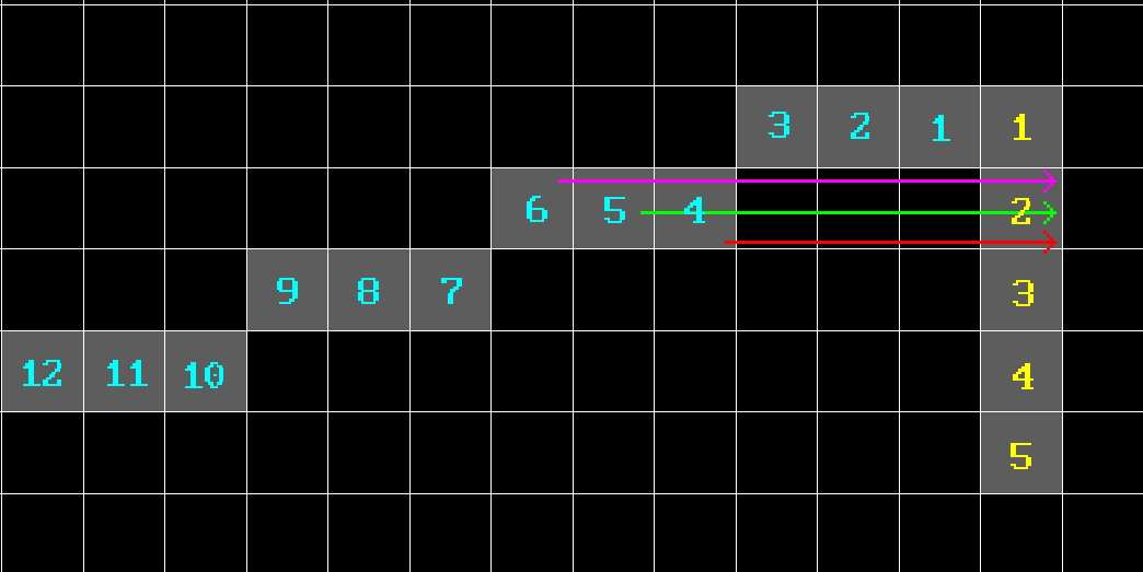
Yellow numbers represent points yielded by the right edge generator, while cyan are the ones yielded by the left one. As you can see, if we do nothing about, line to the yellow point number 2 will be drawn three times: 4-2 (red), 5-2 (green) and 6-2 (magenta). And similar thing will happen with the other points below. And if line is very slanted it will be even worse. And since we’re doing it per pixel, that’s a big waste. But there’s also another thing.
Our generator yields points across Bresenham line. But depending on the type of the line their enumeration order (surprise-surprise, order again) will be different. I illustrated this by enumerating points yielded by left and right edge generators in green and cyan respectively:
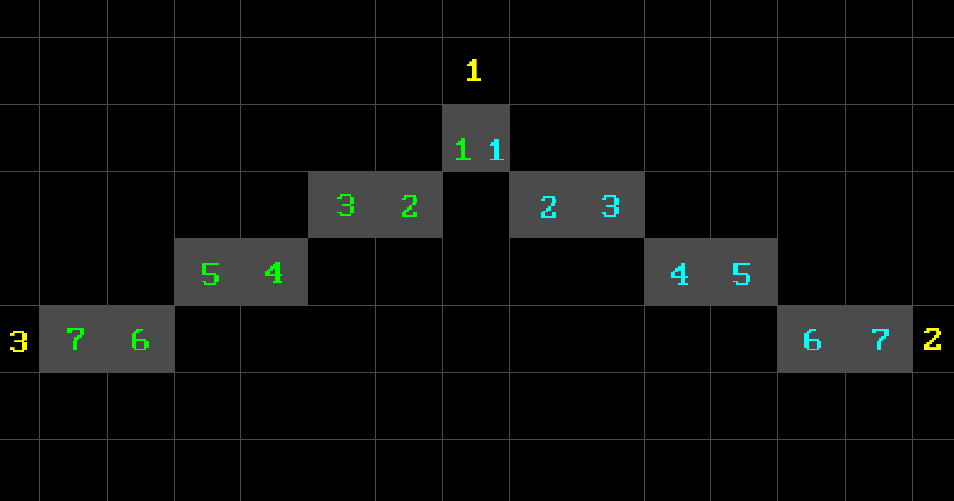
So that’s why I introduced a concept of PointCaptureType, which determines what actual points do we need to connect at what situation. When we’re drawing FB triangle our generators will produce points that go “outside”, but in FT case they’re going “inside”. So we need to take “last” yielded point of a generator in FB case, and “first” one in FT, and only then connect them.
But unfortunately that’s not all: for example point 3 in FB triangle can reside either to the left of point 1 or to the right. I don’t want to draw the picture again, but you can actually see it from the existing one of FB triangle above: just imagine that point 2 is way to the right offscreen and point 3 is located where point 2 is on the picture. This will be the case when point 3 is located to the right of point 1. The same goes for point 2 as well and you can also kinda see it from the existing picture by applying the described method but “the other way around”.
This will change capture type that we need to use for those cases, so we need to take them into account as well. It’s not hard or anything, it’s just a little bit of a hassle, because you had to add couple of conditional checks. The same logic applies to FT triangle and its vertices.
Let’s finally look at the code now (I removed some of the comments to shorten the amount of lines):
void Rasterize(BLG& first,
               BLG& second,
               const TriangleSimple& t,
               TriangleType tt)
{
  BLG::Point* p1 = first.Next();
  BLG::Point* p2 = second.Next();

  if (p1 == nullptr or p2 == nullptr)
  {
    return;
  }

  int x1 = p1->first;
  int x2 = p2->first;

  int y1 = t.Points[0].Y;
  int y2 = t.Points[0].Y;

  PointCaptureType ctLine1 = PointCaptureType::UNDEFINED;
  PointCaptureType ctLine2 = PointCaptureType::UNDEFINED;

  switch (tt)
  {
    case TriangleType::FLAT_BOTTOM:
    {
      //
      // For cases like:
      //
      // 1
      //
      //
      //     3     2
      //
      ctLine1 = (t.Points[2].X <= t.Points[0].X)
                ? PointCaptureType::LAST
                : PointCaptureType::FIRST;

      ctLine2 = (t.Points[1].X <= t.Points[0].X)
                ? PointCaptureType::FIRST
                : PointCaptureType::LAST;

      y2 = t.Points[1].Y;
    }
    break;

    case TriangleType::FLAT_TOP:
    {
      ctLine1 = (t.Points[2].X <= t.Points[0].X)
                ? PointCaptureType::LAST
                : PointCaptureType::FIRST;

      ctLine2 = (t.Points[2].X <= t.Points[1].X)
                ? PointCaptureType::FIRST
                : PointCaptureType::LAST;

      y2 = t.Points[2].Y;
    }
    break;
  }

  for (int currentScanline = y1; currentScanline <= y2; currentScanline++)
  {
    if (p1 != nullptr
    and p1->second == currentScanline
    and ctLine1 == PointCaptureType::FIRST)
    {
      x1 = p1->first;
    }

    while (p1 != nullptr and p1->second == currentScanline)
    {
      if (ctLine1 == PointCaptureType::LAST)
      {
        x1 = p1->first;
      }

      p1 = first.Next();
    }

    if (p2 != nullptr
    and p2->second == currentScanline
    and ctLine2 == PointCaptureType::FIRST)
    {
      x2 = p2->first;
    }

    while (p2 != nullptr and p2->second == currentScanline)
    {
      if (ctLine2 == PointCaptureType::LAST)
      {
        x2 = p2->first;
      }

      p2 = second.Next();
    }

    for (int x = x1; x <= x2; x++)
    {
      SDL_RenderDrawPoint(_renderer, x, currentScanline);
    }
  }
}
This method expects first and second to be the left and right edge of a corresponding triangle respectively in order for the for loop from x1 to x2 to work, so it will be lines 1-3 and 1-2 for FB triangle, and 1-3 and 2-3 for FT.
First we determine what kind of capture type we need. That can be determined quite easily because we can rely on specific order of incoming vertices. We also deal with special cases regarding different capture types as it was described above.
Then we start iterating across given scanlines, which are determined by y1 and y2. We gather points from each of the generators until they change their $y$ and stop being equal to the current scanline value. After that we connect them, bearing in mind current point capture type to avoid overdraw.
And that’s basically it.
I won’t be listing other functions because they’re basically wrappers with different input parameters. And besides I already kinda broke a promise I made to myself in the beginning by saying that I won’t be pasting sheets of code here, but it couldn’t be helped. XD
Please refer to the example project for more detail.
You can use TAB to cycle through preset triangle types. Keys 1, 2 and 3 are used to select individual triangle point and WASD to move it. By pressing F you can toggle between wireframe and filled modes to check out how composite triangle is actually split into basic ones.
OK, this looks good but there’s actually an important issue we need to deal with.
Fill Convention
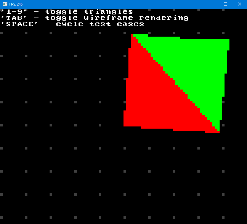
Let’s consider two triangles with the following points:
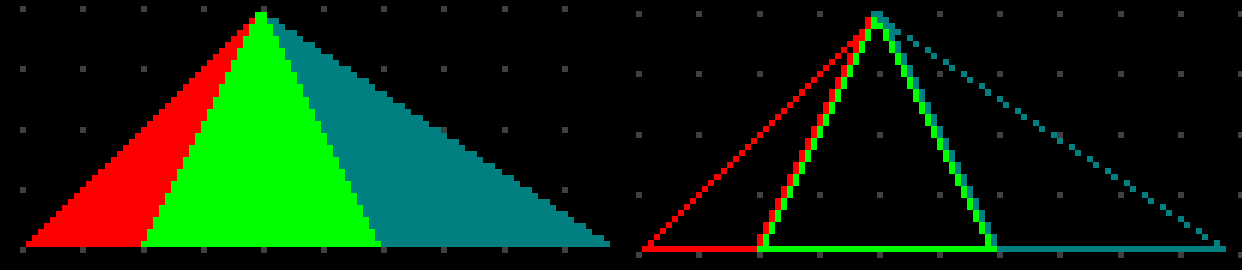
\[\begin{align*} Triangle_1 &=\{ (50, 50, 0), (100, 50, 0), (50, 100, 0) \} \\ Triangle_2 &=\{ (100, 50, 0), (50, 100, 0), (100, 100, 0)\} \end{align*}\]These two triangles have a common edge. Connected triangles like these (called mesh) are basically building blocks of any 3D model. So in this example they will look like this (I colored first one red and second one green and rendered them wireframe to see the problem better):
Now see what happens if we toggle out green triangle:
As you can see, since two triangles share an edge, it gets overdrawn by one of the triangles (green in this case). Now consider the following configuration:
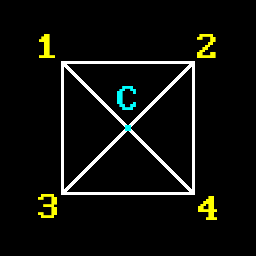
Here edges 1-C, 2-C, 3-C and 4-C will be drawn twice. So we have 4 triangles and 4 overdraws. Your average low-poly model could have 3-5k of triangles and theoretically you could have about that much edge overdraws. This is unacceptable.
Another more explicit issue comes with blending: blending actually relies on drawing order of triangles to properly blend colors, so if you overdraw edges you’ll get incorrect results at those locations, which will likely result in dark lines or something like that. Obviously this will look bad and you don’t want that.
Referring to the Wikipedia article on rasterization mentioned in the beginning, we need for rasterization to have two properties:
-
There should be no holes between adjacent triangles, so that the rasterized area is completely filled.
-
No pixel should be rasterized more than once.
So we need some kind of fill convention to avoid overdrawing of shared edges.
Enter Top-Left Rasterization Rule or Top-Left Rule for short.
Don’t know about you, but when I started researching topic of software 3D rendering, this was the first time I learned about existence of such rule or this whole “fill convention” concept. Like, I never actually gave it any thought, because if you draw stuff with one color (and that’s exactly what you’re going to do in the beginning) everything looks fine. So you might think that, you know, everything works, and move on to next topics. And then imagine you get to blending and then suddenly everything breaks for some reason.
The fact that we’re so used to dealing with out-of-the-box solutions like OpenGL or Direct3D leads to ignorance about how things work on a low level. Like, there’s a library call to draw stuff and it just works, so what else could there be, right? But it all gets really complicated in simple matters when you start considering things on a much lower level… I guess it’s the same story here as with high level programming languages versus low level ones. And again, it doesn’t mean that this whole situation is bad. It just the way thing are nowadays. You don’t have to be an expert in assembly to be a good programmer, but being able to know your way around it is a useful asset to have. Same thing here - you can be a good graphics programmer just by knowing 3D libraries and know how to write shaders. Actually, days when people wrote 3D renderers themselves are long gone. But knowing the intricate details on how it’s done won’t be a useless knowledge for sure.
Anyway, back on topic, if you google “top left rasterization rule” up, you’ll probably immediately stumble upon this article and image:
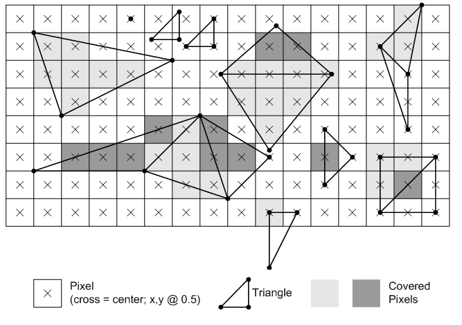
In the article you’ll find two rules that supposed to explain this whole “top-left rule”:
Any pixel center which falls inside a triangle is drawn; a pixel is assumed to be inside if it passes the top-left rule. The top-left rule is that a pixel center is defined to lie inside of a triangle if it lies on the top edge or the left edge of a triangle.
Where:
A top edge, is an edge that is exactly horizontal and is above the other edges.
A left edge, is an edge that is not exactly horizontal and is on the left side of the triangle. A triangle can have one or two left edges.
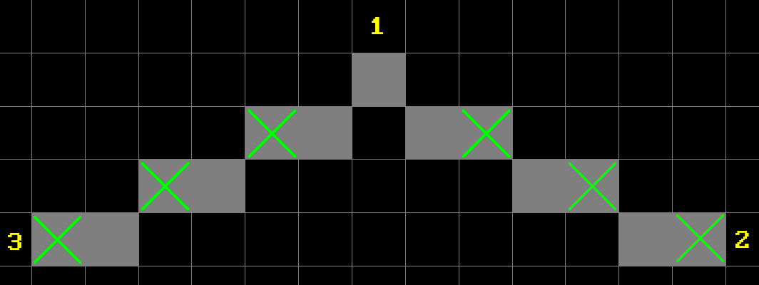
Well, alright, but consider:
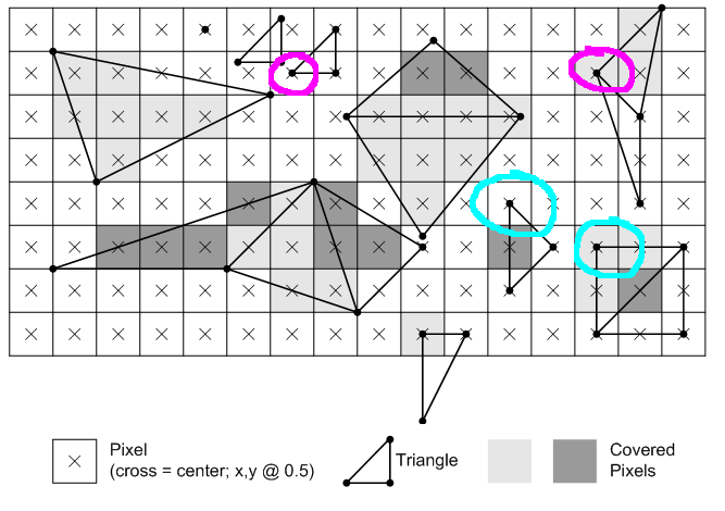
Why one triangle has its corner pixel filled but the other doesn’t (outlined in magenta)? The same question for ones outlined in cyan. If rightmost corner pixel is “top”, so it’s filled, then shouldn’t the other left one also be filled since it’s “left”?
Turns out that it looks like the definition from MS is poorly worded.
Actually Wikipedia article on rasterization elaborates on this (emphasis is mine):
Pixel is rasterized if and only if
- Its center lies completely inside the triangle. Or
- Its center lies exactly on the triangle edge (or multiple edges in case of corners) that is (or, in case of corners, all are) either top or left edge.
You might ask “why is it top-left rule and not bottom-right, or top-right for example?”. Well, first of all, I don’t know. I can only take a guess that top-left rule was chosen because most people read left to right, top to bottom, and so if you chip away rightmost pixel column and downmost pixel row it’s the least noticeable. And second, actually you can choose any type of convention as long as it deals with overdraw problem. Check this test project to see for yourself.
So, let’s implement this top-left rule then.
Because we’re not using subpixel precision, our pixel center always lies inside the triangle, so there goes the first point. And for the second it’s actually super easy, because of our scanline rasterization method that we chose:
-
Draw left and top edge for FT triangle and don’t draw right.
-
Draw left edge for FB triangle and don’t draw right and bottom.
In other words, always draw leftmost point and don’t draw rightmost one, and also don’t draw last scanline. By doing this we will automatically adhere to this top-left rule.
Also, note that in this case we also need to always capture first yielded points from generators in all cases. Why? Suppose we have very slanted edge 1-2 of a FB triangle. It will have its capture type set to LAST, and will contain several points with the same Y scanline for that edge. If this edge is shared with another FB triangle to the right, for that one it will be a left edge 1-3 with capture type set to FIRST. And since we always draw leftmost edges points will thus overlap.
By always chosing FIRST we will ensure that shared edge will always consist of the same set of points and then our “underdrawing” of rightmost pixel will work. So we don’t even need any PointCaptureType stuff in code.
BLG::Point* p1 = first.Next();
BLG::Point* p2 = second.Next();

if (p1 == nullptr or p2 == nullptr)
{
  return;
}

int x1 = p1->first;
int x2 = p2->first;

int y1 = t.Points[0].Y;
int y2 = t.Points[0].Y;

switch (tt)
{
  case TriangleType::FLAT_BOTTOM:
    y2 = t.Points[1].Y;
    break;

  case TriangleType::FLAT_TOP:
    y2 = t.Points[2].Y;
    break;
}

for (int currentScanline = y1; currentScanline < y2; currentScanline++)
{
  //
  // Always get "first" point no matter the direction.
  //
  if (p1 != nullptr and p1->second == currentScanline)
  {
    x1 = p1->first;
  }

  while (p1 != nullptr and p1->second == currentScanline)
  {
    p1 = first.Next();
  }

  if (p2 != nullptr and p2->second == currentScanline)
  {
    x2 = p2->first;
  }

  while (p2 != nullptr and p2->second == currentScanline)
  {
    p2 = second.Next();
  }

  for (int x = x1; x < x2; x++)
  {
    bool isTop  = (tt == TriangleType::FLAT_TOP
               and currentScanline == y1
               and x >= x1);
    bool isLeft = (x >= x1);

    if (isTop or isLeft)
    {
      SDL_RenderDrawPoint(_renderer, x, currentScanline);
    }
  }
}
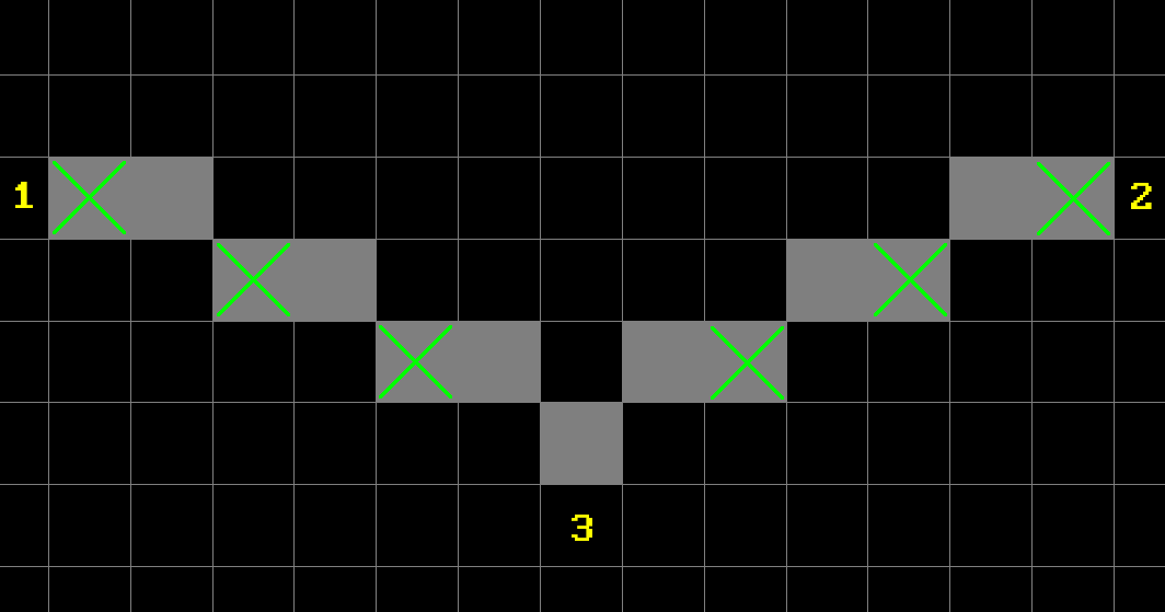
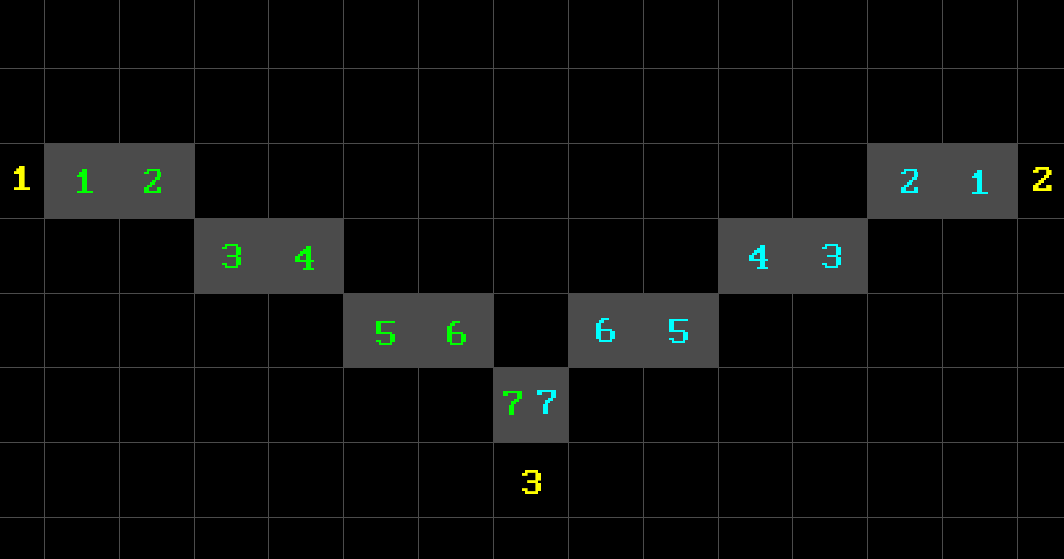
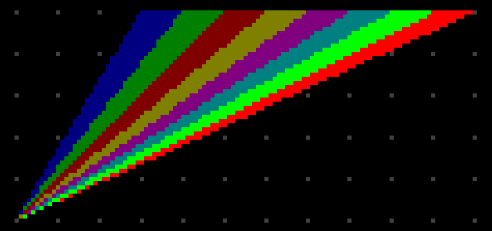
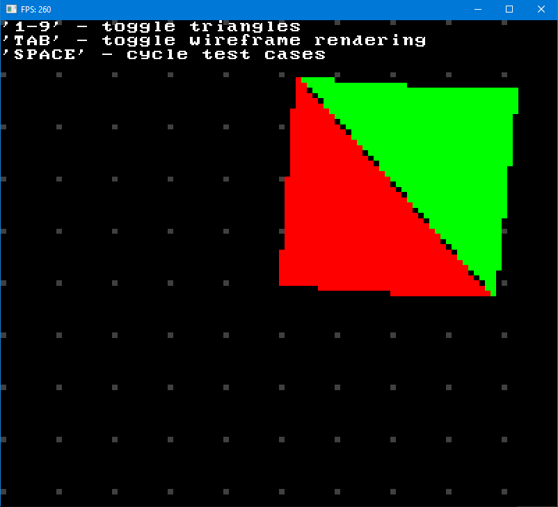
Well, it works, I guess. At least it does seem to fill triangles correctly in certain configurations, but in some edge cases we get artifacts like these (numbers in red are triangles that were hidden):
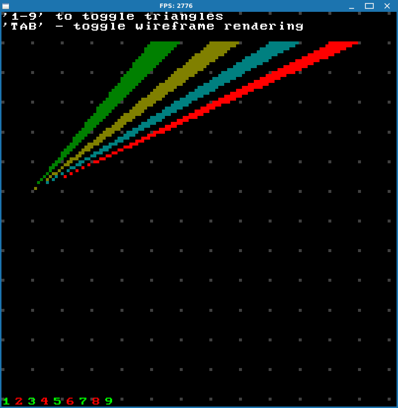
And it’s actually OK since there’s nothing we can do about it really. Because all these triangles start from one point, and on top of that everything is super tight, somebody has to draw somewhere while others have to skip it. At least if we draw all triangles the area gets filled uniformly without gaps and / or overdraws:
So I guess maybe it works? At least for meshes?
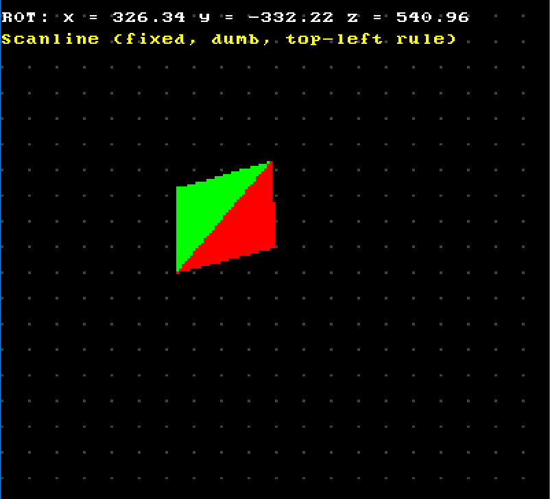
There’s only one way to verify that. But to do that we will have to run ahead a little bit. Let’s actually construct a simple quad with two triangles that have shared edge, project it and add ability to transform it by rotating in three dimensions, and then see what happens. Don’t worry, we’ll go over projection and transformations later, it’s not important right now. The goal here is to check that everything still gets drawn correctly after polygon undergoes irregular transformation and its vertices end up at whatever locations they end up. Because later our triangles will be transformed constantly and in different ways, so it’s better to check that they are rasterized correctly at the earliest stage of our 3D renderer, so that we don’t stumble across this problem while researching said transformations and / or projection, for example, and then have to stop what we’re doing and go and solve this rasterization problem.
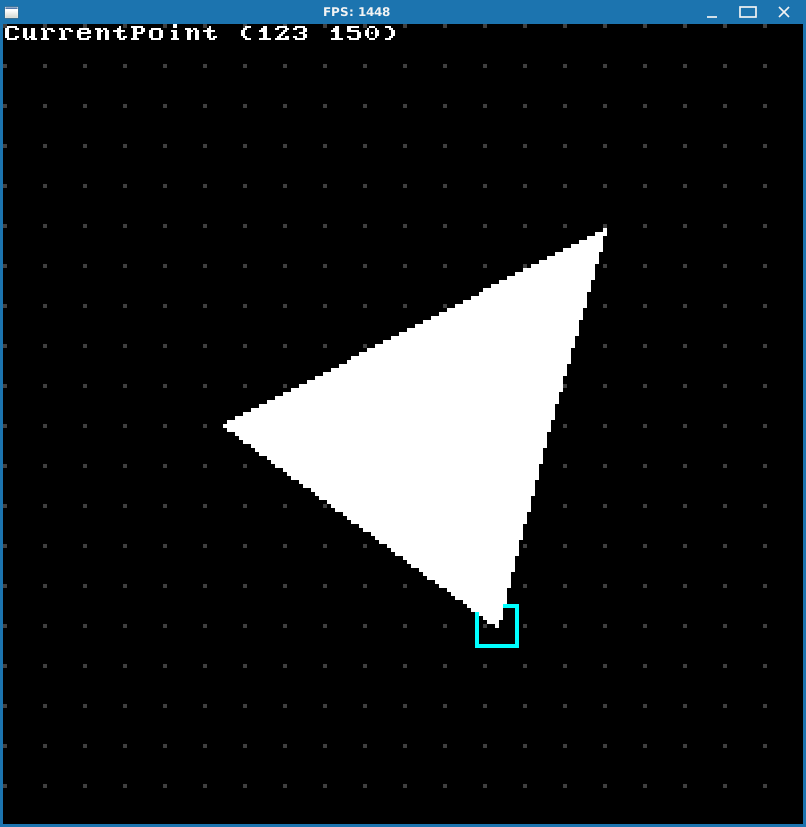
I wrote simple test program that allows you to rotate said quad around three dimensions, and very quickly we arrive at one of these situations:
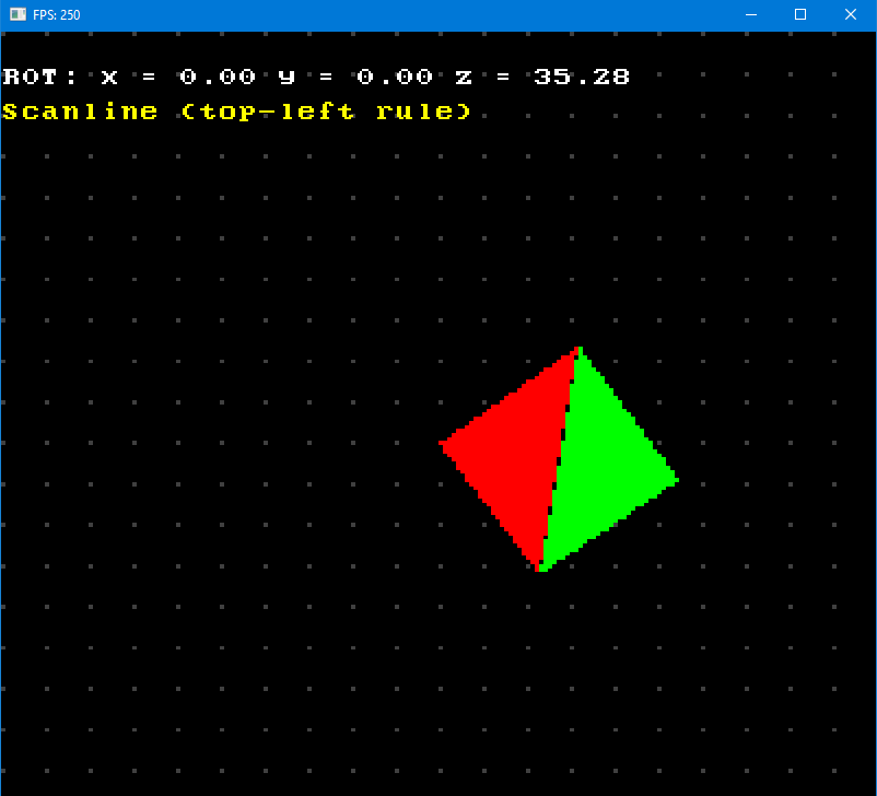
So it doesn’t work. Why?
Depression Quest
I gotta be honest, this was a very discouraging moment. Of course, deep inside I was a little doubtful, because, c’mon, it can’t just work at first try, right? Who do you think you are? But still, I had very high hopes for this approach and was confident that it will work. I mean, how can it not? We implemented Bresenham line algorithm by using lots of math in the process, so that is, like, extremely substantiated. And we checked that it indeed works. Then we put that in generator so we can get those points iteratively - nothing fancy here. We handled different capture type modes for generators, went over every possible edge case. So all was left to do is just to construct a loop, take out new points from generators until there are no more left, and connect them. We even checked that rasterization works on a single triangle for every kind of it. And since we’re doing scanline rasterization we can super easily satisfy this top-left fill convention rule by not drawing rightmost and downmost pixel lines. And we’re also working with integers all over the place, so there shouldn’t be any rounding error induced artifacts or anything like that.
So where did those gaps (called dropouts by the way) come from?!
Was all of my work just in vain? And what should I do with these articles now? Delete them?
After thinking about it for some time I had thoughts of just skipping this problem and write “I couldn’t do it” or something like that and go ahead with different rasterization method, but fortunately everything resolved positively in the end.
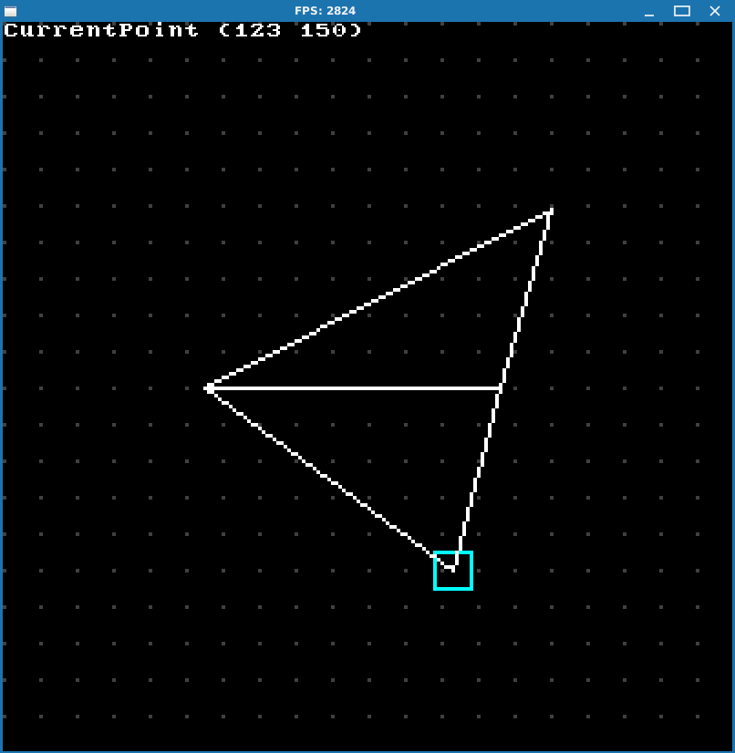
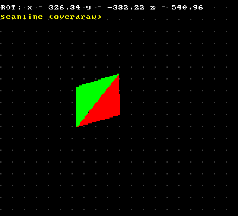
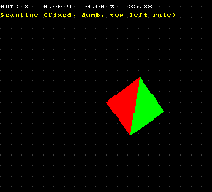
After some fiddling around I found out that in certain cases even the overdraw version of the algorithm produces dropouts:
At first I had no possible explanation for this phenomenon. Situation was also complicated by the fact that in certain configurations everything looked fine:
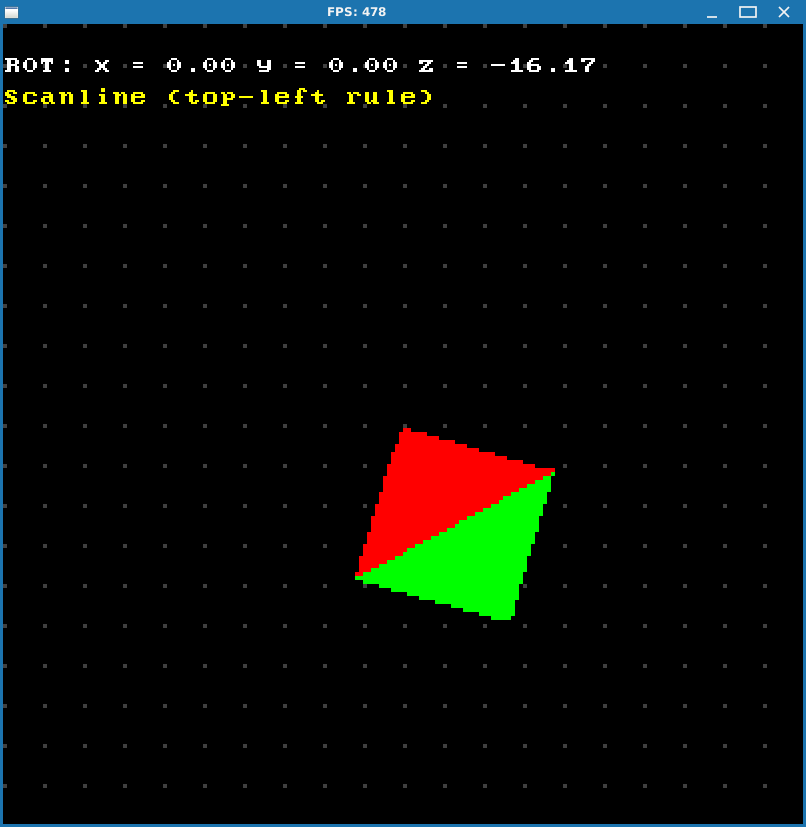
But still, it seemed like bug manifested itself only in composite triangles.
OK, so I started thinking. Suppose the problem lies in rasterization of composite triangles. What is the “weakest” point, so to speak, in that part of the algorithm? Obviously, it’s the calculation of the splitting point. After that we have two triangles that we supposedly know how to raster, and we delegate their drawing to already existing methods. Sounds good so far. But somehow we still end up having problem with dropouts. So maybe there’s something wrong with calculation of this splitting point since it basically gets produced out of thin air? Sure, it’s supposed to lie on the edge, but that’s in analytical world. In discrete world - who knows, right? So maybe our problem lies in unstable calculation of this splitting point?
Well, there’s only one thing left to do here: debug.
Unfortunately debugging of graphical applications is quite different from “traditional” debugging and sometimes might not even be possible. In “traditional” applications (like daemons or some kind of services) when you have a bug you can usually always pinpoint its possible origin in code. Most often you have some kind of business logic that does different things depending on some conditions, and bug happens inside one of them. So you can set a breakpoint at that condition. Then you run your application in debug mode, reproduce the bug, hit a breakpoint and proceed from there.
But in graphics you have this infinite drawing loop. So it’s problematic to just set a breakpoint and wait for something. Because, for example, like in our case: we have dropouts in certain configurations, but not always. So we would like to somehow set a breakpoint and then hit it at the time when we have a dropout in our rasterization. But how do we set such a condition? To check in the debugger what points gets produced from generators we need to set a breakpoint somewhere around beginning of the rasterization function. But we will always hit it because our draw loop is infinite and gets called every frame! So we will have to constantly hit “continue” in the debugger while at the same time trying to position our quad into one of the problematic configurations. Obviously, it is impossible to debug this way. Sometimes you could have some kind of side variable that happens to receive specific value at the time your case occurs. In this situation you can set breakpoint at the moment when this variable gets that specific value and thus hit a breakpoint at certain time that you need. But such situations are quite rare and not always this cooperative.
Fortunately, here we can isolate one of the cases with dropouts, and then in separate project walk the whole rasterization routine inside the debugger, since it will be drawing the same thing every frame anyway. That’s exactly what I did.
So I made another test project and isolated one of the buggy cases by hardcoding values of transformed vertices for the triangle from test project with rotation that I’ve just described above.
My goal was now to somehow fix my rasterizer and if dropouts in this isolated case were to disappear, I could at least hope that I thus fixed the problem altogether.
So I wrote down all the points that get produced along this shared diagonal from both FT and FB part of red and green triangles (I won’t list them here for sake of brevity), and, well, long story short - turns out our Bresenham algorithm, that we so thoroughly implemented, has an unobvious bug:
If you break a line into two segments, it’s not guaranteed that set of points from those two segments will belong to the set of points from the whole line.
Don’t ask me why - I have no fucking idea. I mean, you saw it: I dedicated the whole chapter alone to this Bresenham drawing algorithm, it looks bulletproof. I thought that if it worked - it worked. I never imagined that set of points could differ if we just basically iterated in parts across the same line. And now it turns out to be the cause of rasterization bugs.
Anyway, I reproduced this bug by calculating slope of the diagonal line from this isolated buggy quad configuration, and then using it to get unrelated set of points from 0 to 10:
>>> (13.6384 - 10.1522) / (56.742584 - 53.8462)
1.2036387440339413
>>> for x in range(0, 10):
...   y = 1.2036387440339413 * float(x);
...   print(f"{x} {y}")
...
0 0.0
1 1.2036387440339413
2 2.4072774880678827
3 3.610916232101824
4 4.814554976135765
5 6.018193720169707
6 7.221832464203648
7 8.425471208237589
8 9.62910995227153
9 10.832748696305472
Then I primed three generators: one from (0, 0) to (9, 10), second one from (0, 0) to (3, 3) and third one from (3, 3) to (9, 10).
And this is what I got:
(0, 0) - (3, 3)

(0, 0)
(1, 1)
(2, 2)
(3, 3)
-----
(3, 3) - (9, 10)

(3, 3)
(4, 4)
(5, 5)
(6, 6) !
(6, 7)
(7, 8)
(8, 9)
(9, 10)
-----
(0, 0) - (9, 10)

(0, 0)
(1, 1)
(2, 2)
(3, 3)
(4, 4)
(5, 5)
(5, 6) !
(6, 7)
(7, 8)
(8, 9)
(9, 10)
-----
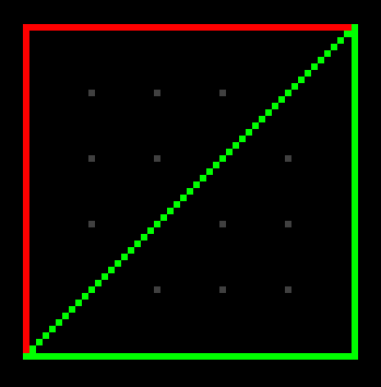
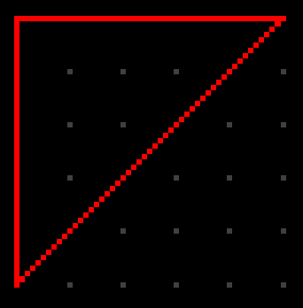
As you can see, we have different set of points, even though the line is the same! In the picture below every points get +10 to their components just because it’s hard to see things properly at (0, 0) which is upper left corner of the screen:
![]()
So what we have is that if we have two composite triangles that share an edge, this shared edge gets split 4 times: two line segments for one triangle and another two for the other. And since set of points that gets produced for those triangles is not guaranteed to belong to the same set of points that is produced for the whole shared edge itself, scanlines can sometimes not cover enough pixels across because top left rule forces all rightmost pixels to not get drawn. Some scanlines cover enough pixels so that they become connected to the adjacent triangle if their rightmost pixel is not drawn, but sometimes a scanline can already be connected to the edge of adjacent triangle, but then the top left rule forces it to drop its rightmost pixel, leaving a gap. Even worse, most of the time those splitting points are far from each other, which only increases the probability of divergence, so to speak. Everything becomes a mess. No wonder we have dropouts!
Closure
At this point I had enough and was ready to just give up. Delete these two chapters and say something like “I tried but failed”, but still decided to give it one more try. I was already set upon different rasterization algorithm anyway, but wanted to have closure on this. Nobody likes unfinished business, right?
So this time, I thought, I’ll concentrate on ensuring the correctness of the algorithm and ignore any efficiency / performance issues. I just needed to prove to myself that my idea with generators wasn’t wrong. It just happens to be some weird bug with line splitting that screws it up.
So, we’re going to avoid it.
Instead of calculating the splitting vertex using mathematical formula, we’re going to derive it from existing points. Let’s look at MR triangle again as an example:
What we’re going to do is gather all points for 1-2 from generator and save it in unordered map by $y$ scanline. It’s obvious that splitting point X will have scanline $y$ value the same as $y$ coordinate of point 3. So we just get point at that scanline $y$ position from our unordered map. And then manually connect points from generators 1-3 and 1-X (which is basically part of points from generator 1-2), and do the same for 3-2 and X-2.
Anyway, I won’t bother you with details, you can check out the project here in all its shitcode glory. And, surprisingly, it worked! My isolated buggy quad case was now rendered without dropouts:
I also checked couple of previous problem cases and everything was fixed there as well:
OK, now it works and I can finally let it go.
Conclusion
Actually when I first encountered these dropout bugs I went ahead and looked up scanline rasterizer from this video (I mentioned this channel at index page) to see how it worked there, because it didn’t seem to be any problems in that implementation. Turns out it was super simple and basically used slightly modified line equation to work out new points. Most importantly it used pixel centers for sampling, i.e. (x + 0.5, y + 0.5) coordinates, which actually makes line look nice, so using pixel center probably reduces floating point errors in calculations. I implemented it in another test project, so you can check it out if you want, I won’t be explaining it here.
Original goal was to use Bresenham algorithm to avoid floating point calculations and division and thus hopefully achieve a little boost in performance, but it didn’t work out well enough, as you just saw. But if we ditch this notion of “expensive floating point calculations” we can still use scanline rasterizer if we want to, just by implementing it differently.
But we won’t.
Read next part to find out why.